3D Topo Generator is a web application for creating 3D printable terrain models from digital elevation data.
Select any area on Earth, configure your model, and choose the processing workflow that best fits your project.
You can also upload GPX, KML, or GeoJSON tracks, visualize recorded activities, associate them with manually drawn bounding boxes,
and turn selected routes and pins into physical details on supported exports.
💡 Perfect for: Hikers, runners, cyclists, sailors, architects, educators, geologists,
cartographers, and 3D printing enthusiasts who want to preserve a landscape or recorded journey as a physical model.
When to use professional GIS/CAD tools instead
If you need very large geospatial pipelines, advanced GIS analysis, or highly custom production modeling, tools
like ArcGIS/QGIS/Blender remain better suited. 3D Topo Generator is optimized for fast terrain-to-print workflows
with minimal setup.
🖥️ Browser vs ☁️ Cloud: Two Workflows, One Simple Choice
3D Topo Generator offers two purpose-built ways to create terrain. Browser mode turns your
device into an interactive creative workshop with the richest export toolkit. Cloud mode moves terrain computation
away from your device, applies no fixed app-defined geographic-area ceiling, and delivers the result
asynchronously through Cloud Jobs. This ability to generate terrain far beyond normal browser CPU and memory
limits is Cloud Processing's defining advantage. One shared credit balance supports both workflows.
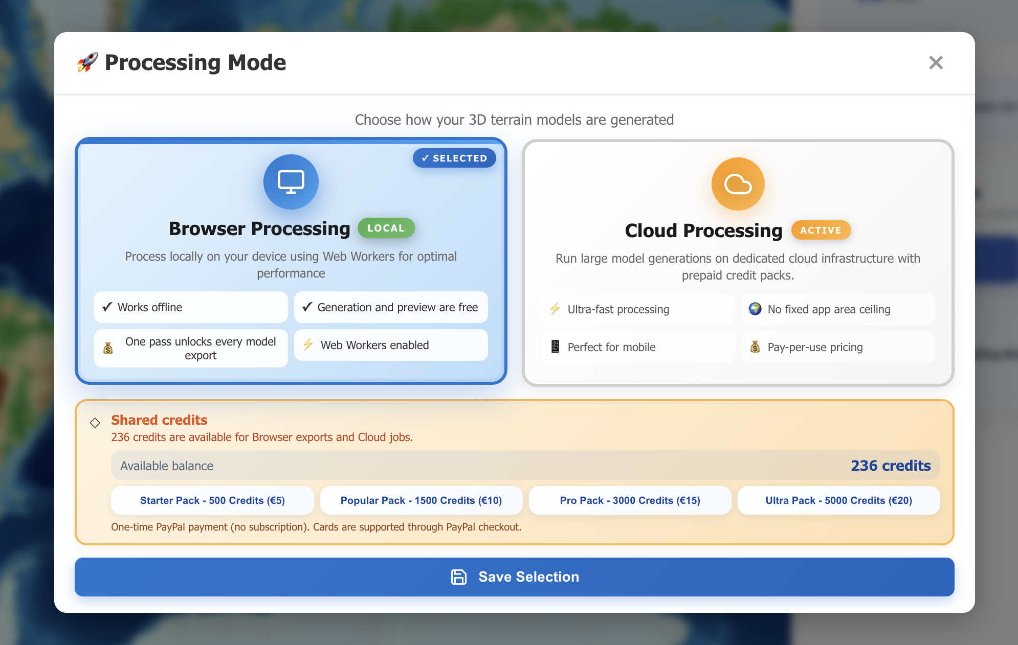
The Processing Mode window keeps workflow selection, the shared balance, and optional credit packs together in one clear view.
Capability
🖥️ Browser Processing
☁️ Cloud Processing
How processing works
Generation location
Local Your browser and Web Worker process the model on your device.
Cloud The backend processes an asynchronous job for your account.
Geographic area scalability
Device-dependent Practical project size is constrained by the browser, available RAM, CPU, and DEM complexity.
No fixed app ceiling Designed for terrain areas far beyond normal browser limits, with processing performed by the backend.
Keep the page open during generation
Required The browser must remain open until local processing finishes.
Not required After submission, the job continues without using your device.
Processing cost
Free creation and preview Generation, every visual style, map overlays, PNG, and project JSON are free. One pass unlocks all files for an exact configuration.
Credits per job Prepaid, pay-per-use credits with no subscription.
Printable model capabilities
Solid terrain model
✓ Yes Generated locally from the selected DEM.
✓ Yes Generated remotely from the selected DEM.
Repair missing sea feature around coastlines
✓ Yes Optional conservative repair for land DEMs that encode surrounding sea as NoData or flat zero values.
— No The control is disabled and Cloud retains its established gap-interpolation pipeline.
GPS track printed on terrain
✓ Yes The selected route is clipped, DEM-sampled, and raised above the terrain.
— No Selected tracks stop Cloud submission before credits are charged.
Pins printed on terrain
✓ Yes Visible pins inside the box can be included in supported exports.
— No The current Cloud terrain STL does not contain pins.
Topographic elevation bands
✓ Yes Adaptive, Equal Step, and Coastal Preserve modes are available for segmented output.
— No The current Cloud output is not split into printable elevation-band parts.
Downloadable files
Portable project and purchased restoration
✓ Yes Download exact JSON, use Set Box for precise limits, import later, and restore locally archived purchased models without paying twice.
— Not applicable Cloud Jobs already preserve their own remote request and artifact status.
Terrain-only STL
✓ Yes Available from the local preview.
✓ Yes Available from Cloud Jobs when processing completes.
Combined terrain + tracks + pins STL
✓ Yes Selected elements are normally Boolean-unioned as one validated solid; a quiet part-preserving fallback keeps exceptional routes downloadable.
— No Cloud currently returns terrain only.
Watertight segmented terrain 3MF
✓ Yes Base and elevation bands remain separate aligned solid objects.
— No 3MF packaging is not part of the current Cloud worker.
Segmented 3MF + Map Elements
✓ Yes Terrain bands, tracks, and pins remain separate aligned objects.
— No Tracks, pins, and 3MF are Browser-mode exports today.
Slicer object names
Semantic 3MF uses base, topo-N, track[-N], and pin[-N].
Single model The current Cloud artifact is one terrain STL without multipart 3MF objects.
Printing guide TXT
✓ Yes Manual filament-change guidance is generated with the model.
— No The current Cloud job produces only a terrain STL.
Workflow and delivery
Progress information
✓ Detailed Live stages and percentages appear during generation.
Job status Cloud Jobs shows Submitted, Processing, Completed, or Failed.
3D preview before download
✓ Yes The completed terrain opens in an interactive model-first workspace with generated-model, hillshade, real-slope, and contour/topographic views.
— No The completed STL is downloaded directly from Cloud Jobs.
Cancel while processing
✓ Yes Local generation can be cancelled immediately.
— No The current asynchronous job has no in-progress cancel action.
Download retention
Your files Downloaded files remain under your control.
1 day Cloud artifacts are intended for short-term download.
Best suited to
Advanced projects Small/medium areas, imported GPS routes, pins, and maximum export control.
Area at scale Very large terrain-only areas and work that should continue away from your device.
Swipe horizontally to explore the full comparison.
Cloud's key advantage—area at scale: the application does not impose a fixed maximum
geographic area on Cloud jobs. This makes Cloud the preferred workflow when a terrain request is too large for
reliable in-browser CPU or memory processing. Real-world completion still depends on the selected DEM's
coverage, OpenTopography request and rate limits, backend timeouts, and sufficient credits; “no fixed app
ceiling” therefore means scalable by design, not a guarantee that every arbitrarily large external data request
can complete.
Why the Processing Cores Are Kept Separate
The two modes solve different engineering problems, so they intentionally follow separate execution paths.
🖥️ Browser Core: the creative workshop
It is optimized for instant interaction, on-device processing, local previews, and feature-rich model
composition. This is where GPX, KML, and GeoJSON tracks, pins, merged STL, watertight multipart 3MF, and
printing guides can work closely with the map.
☁️ Cloud Core: the dependable remote worker
Its primary strength is scalable geographic coverage without a fixed app-defined area ceiling. It combines
backend DEM processing with authenticated, account-scoped jobs, credit safety, failure refunds, temporary
artifact storage, and reliable delivery through the Cloud Jobs dashboard—even when the user's device is no
longer doing the heavy work.
Keeping the cores separate lets each mode evolve around its real strengths. It also prevents a browser-only
feature from being silently ignored by a paid Cloud job: unsupported combinations are clearly blocked before
credits are charged. The result is a transparent choice today and a safe foundation for future Cloud capabilities.
Our friendly recommendation: choose Browser Processing for personal routes,
pins, advanced 3MF projects, and maximum export control. Choose Cloud Processing when your
priority is generating terrain across areas beyond practical browser limits while freeing your device after
submission.
You can switch modes whenever your next model calls for a different balance of creativity, area size, time, and convenience.
⚡ Performance & Processing
Terrain generation can be demanding, especially when a large geographic area produces a dense elevation grid.
Use these practical guidelines to balance detail, processing time, and device resources. If you have not chosen a
workflow yet, start with the Browser vs Cloud comparison.
Relative Area Workload Guide
Area Size
Typical Browser Workload
Recommendation
< 25 km²
Light
Usually a comfortable Browser starting point
25-100 km²
Moderate
Generally suitable for Browser mode on a modern device
100-200 km²
Heavy and device-dependent
Browser remains available; consider stronger reduction or Cloud mode
> 200 km²
Very heavy and device-dependent
Cloud is usually the safer choice; Browser is not artificially blocked
These bands describe relative workload rather than guaranteed completion times. DEM resolution and coverage,
reduction factor, smoothing, map elements, network speed, available memory, CPU, and browser limits can make two
boxes with the same area behave very differently.
⚠️ Large Area Warning
When creating a bounding box larger than 100 km²,
you'll see a Browser warning. This is a safety precaution and an advisory message—not a block and not a
statement that Browser Processing will not work. It simply explains that downloading the DEM and generating
the model may take longer or could fail depending on the selected area, DEM complexity, available memory, CPU,
and browser limits. You can continue locally, optionally increasing the resolution reduction factor to reduce
the workload, or switch to Cloud mode to move beyond the device's practical CPU and memory limits without a
fixed app-defined area ceiling.
Generation Phase (70-90%) - Web Worker creates 3D mesh in a background thread; UI stays responsive
Preview Phase (90-100%) - Creating 3D visualization; brief final processing
Instant cancellation - Cancel button works immediately at any stage
Shared Credits and Two Clear Prices
The balance in the top account area, below the processing-mode switch, is shared by Browser exports and Cloud
jobs. Buying a pack adds credits once; you then decide which workflow should spend them.
🎁 250-credit welcome gift: every registered account can receive this promotional gift once.
Eligible new and existing users must register or sign in no later than
31 August 2026 at 23:59 Europe/Rome.
Use the gift in either workflow: unlock all Browser downloads for an exact model
configuration, or spend it on remote Cloud terrain jobs. Receiving the gift does not force a processing mode
or activate Cloud mode; the user remains in control. Credits successfully awarded before the deadline remain
in the wallet after the campaign ends.
Browser Export Pass: generation and preview are free. One purchase unlocks every applicable STL, 3MF, and printing guide for that exact configuration, with unlimited download retries.
Cloud job: credits pay for an asynchronous remote terrain job and its temporary STL delivery.
Compare both options at a glance. The app always shows the exact credit price before a purchase or job submission.
Area (km²)
Browser Export Pass
Cloud Job
20
26 credits
54 credits
50
28 credits
60 credits
100
30 credits
70 credits
200
35 credits
90 credits
500
50 credits
150 credits
1,000
75 credits
250 credits
Credit Calculator
Enter a custom area to compare the Browser Export Pass and Cloud Job prices together.
Browser Export Pass
— credits
Cloud Job
— credits
🌐 Browser Support
For the best experience, use an up-to-date version of one of the browsers listed below. The app uses modern
browser features for file handling, local processing, storage, and 3D graphics. The size and complexity of the
terrain models you can process also depend on your device's memory and performance.
Google Chrome or Microsoft Edge
Mozilla Firefox
Safari on macOS or iOS
Google Chrome on Android
⚠️ Note: Internet Explorer is not supported. Please use a modern browser for the best
experience.
🧭 Welcome Guide & Workspace
Welcome Guide
When you first access the main application, a welcome modal appears with the 4 core steps to
get started:
Get Your API Key: Configure your OpenTopography API key via the user menu
Select Your Area: Navigate the map or upload a GPX, KML, or GeoJSON route to locate your activity
Create a Bounding Box: Select 4 points on the map or enter exact limits
Generate & Download: Customize settings and create your 3D model
You can close this modal anytime and optionally hide it for the current session.
Understanding the Workspace Layout
The workspace is organized for quick terrain selection and fast iteration:
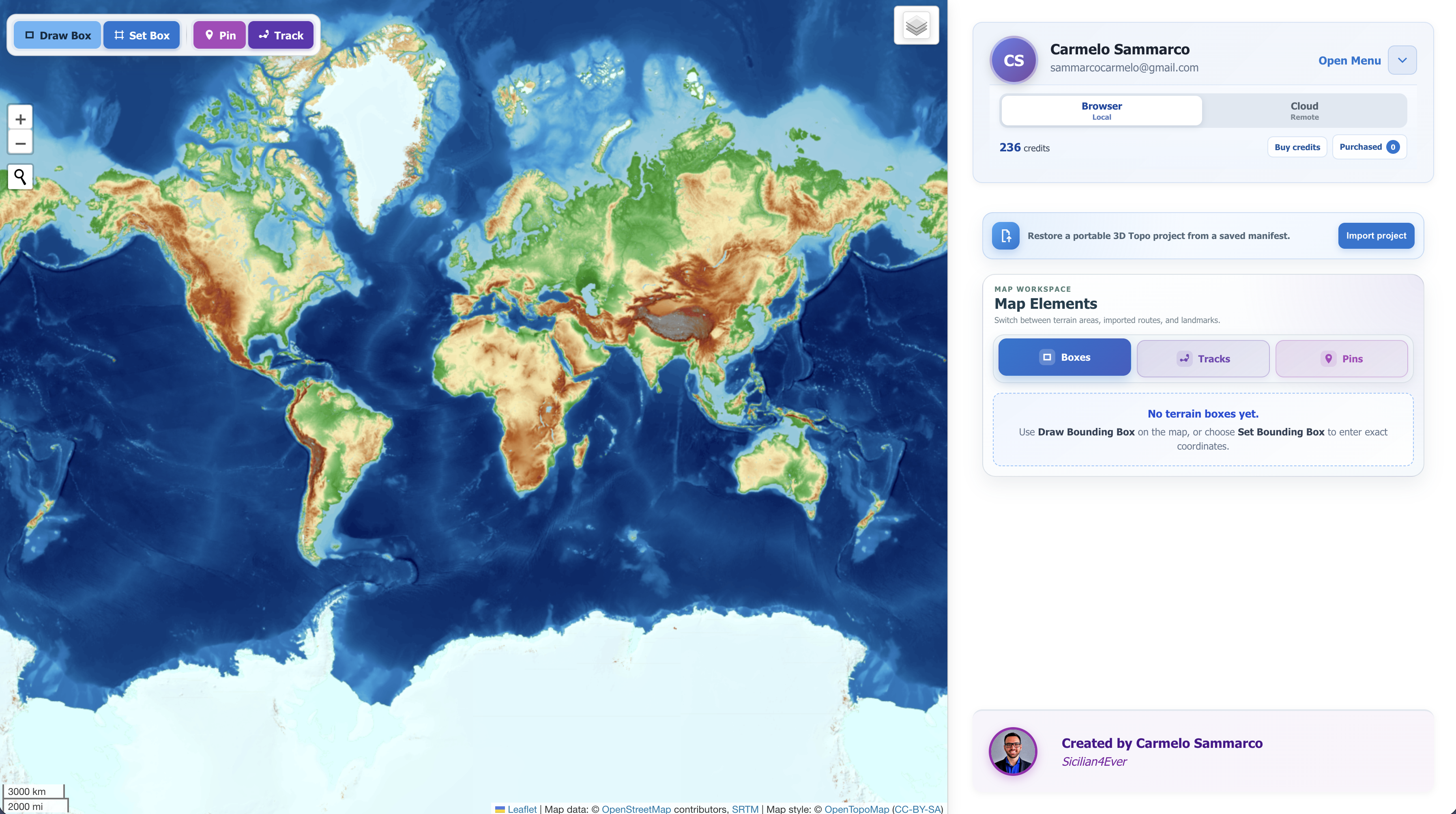
Desktop Layout
Left Side (65%): Interactive map with one compact floating toolbar. Icons, a divider, and short Draw Box / Set Box / Pin / Track labels distinguish the blue box tools from the magenta/purple/indigo element tools; full names remain available as tooltips
Right Side (35%): Control panel with integrated user menu, a compact portable-project import callout, and one space-saving Map Elements card with Boxes, Tracks, and Pins tabs
Main desktop workspace: the map remains the primary canvas while account, processing, project, box, track, and pin controls stay organized in the right panel.
Mobile Layout
Top: Fixed header with panel toggle button and user avatar menu
Main Area: Full-height interactive map optimized for touch navigation and search-first location workflow
Panel Quick Actions: matched controls for drawing or precisely entering a box, followed by pin placement and GPS-track upload
Collapsible Panel: Tap ☰ Panel to open the full controls sheet, switch the Map Elements tab you need, and use ✕ Close Panel to return to map focus
Map Elements Tabs
The single Map Elements card replaces three long simultaneous lists. It always opens on
Boxes, with Tracks second and Pins third. Selecting a tab
reveals only that list; nothing is deleted or disabled when another tab is active. Count badges update as
elements are added or removed. Keyboard users can move between tabs with Left/Right arrows and jump with Home
or End.
When a list is empty, the panel remains useful instead of appearing blank. A colour-matched guidance card
identifies the next action: Draw Bounding Box or Set Bounding Box for Boxes,
Upload Track for GPX/KML/GeoJSON routes, and Place Pin for landmarks. The
guidance disappears when the first item is added and returns automatically if the last item is removed.
Bounding Box Buttons (What They Do)
Draw Box: starts four-point area selection on the map. Its full tooltip is Draw Bounding Box.
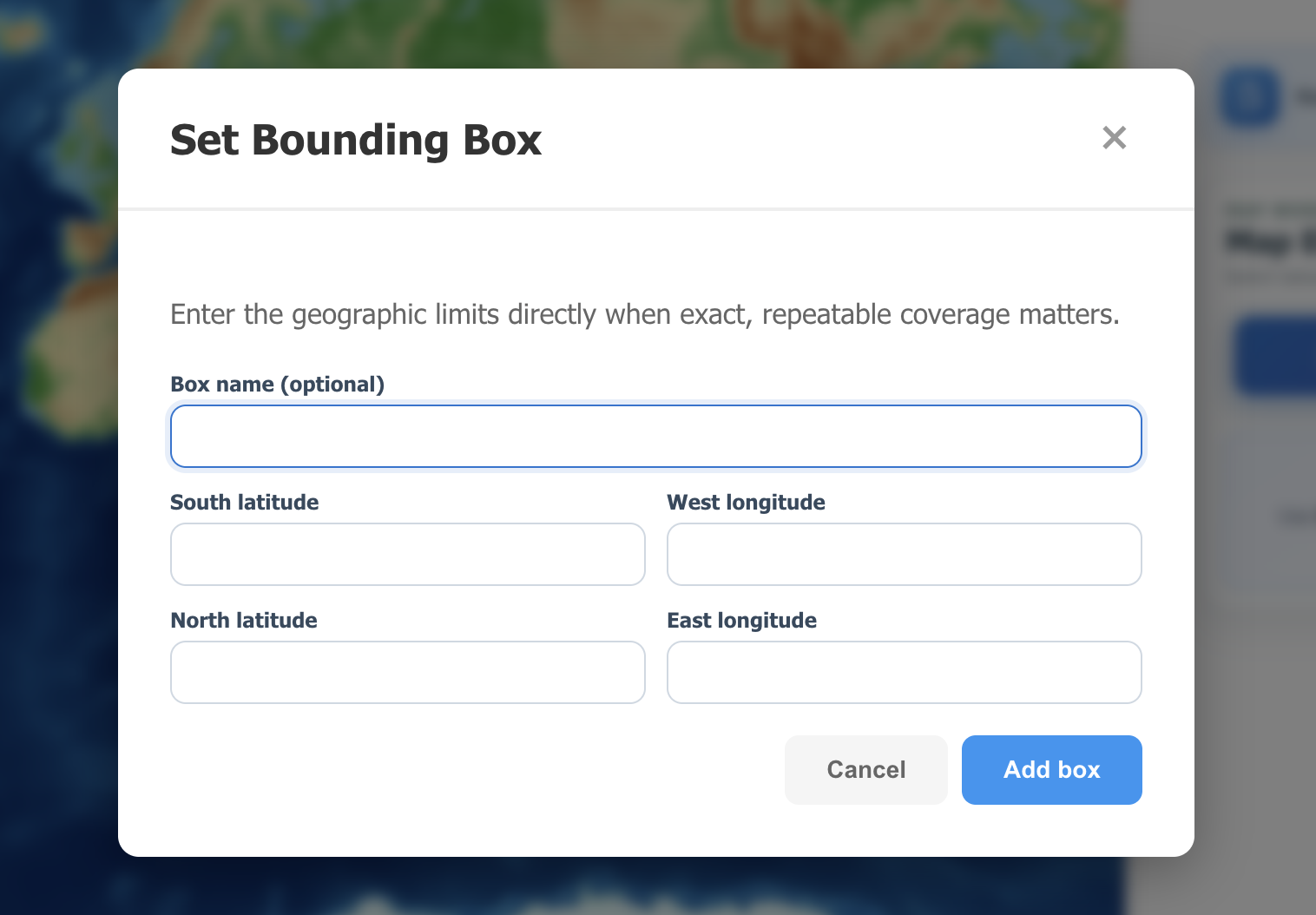
Set Box: opens the precise south/west/north/east entry form beside the drawing action. Its full tooltip is Set Bounding Box.
▶ / ▼ (Collapse): hides or expands one box details panel to keep the list clean.
🔍 Zoom to box: centers and fits the map on that bounding box.
Rename: changes the box title for better project organization.
Hide / Show: toggles box visibility on the map without deleting it.
Delete: permanently removes the selected bounding box.
Pin Buttons (What They Do)
Pin: enters pin-placement mode from the unified map toolbar; choose the Pins tab to manage the resulting list.
👁️ All: toggles visibility for all pins at once.
🔍 (Pin list): zooms directly to the selected pin position.
✏️ (Pin list): edits pin tag, color, and size.
👁️ / 👁️🗨️ (Pin list): shows or hides an individual pin.
🗑️ (Pin list): deletes the selected pin.
GPS Track Controls (What They Do)
Track: beside Pin in the unified map toolbar, imports one or more GPX, KML, or GeoJSON line files and immediately draws their routes. Choose the Tracks tab for the resulting route list and controls.
⌖: fits the map to the complete selected track.
◉ / ◌: shows or hides the route without deleting its stored data or box association.
✎: renames the imported track.
✕: deletes the track from the map and local IndexedDB storage.
Activity: classifies the route as trekking/hiking, running, cycling, cruising/sailing, skiing, or other.
Map/print color: sets the Leaflet line color and records the intended print color for the track.
Track width / Raised height: controls the physical millimetre dimensions of the printable route.
💡 Integrated User Menu: Includes OT API Key, Processing Mode, Cloud Jobs, and Log Out.
On desktop, it is collapsible and keeps your preferred open/closed state.
〰 GPS Tracks & Printable Routes
The GPS Tracks workflow turns a recorded surface activity into both a map guide and a physical feature on the
terrain model. It is designed for trekking, hiking, running, cycling, cruising, sailing, skiing, and similar
activities recorded on land or sea.
Step 1📥
Import and inspect
Upload GPX 1.0/1.1, KML, or GeoJSON tracks. The app validates the file, renders every supported line segment, calculates distance, identifies the source format, and zooms to its geographic extent.
Step 2📐
Frame the terrain manually
Draw the bounding box yourself after seeing the route. This keeps full control over surrounding landscape, aspect ratio, and print composition.
Step 3✂️
Associate and clip
Each box identifies intersecting tracks as Complete or Partial. Partial line segments are clipped exactly at the model boundary.
Step 4🖨️
Print on the terrain
The route becomes a smooth, rounded, watertight sweep that follows the exact terrain surface and embeds slightly for reliable slicing and adhesion. Circular activities close as one continuous loop without overlapping end caps.
Supported Track Formats and Content
GPX: GPX 1.0/1.1 .gpx files using trk → trkseg → trkpt or rte → rtept, including multiple segments.
KML:.kml files using LineString geometry in placemarks, documents, folders, or MultiGeometry, plus Google Earth gx:Track.
GeoJSON:.geojson and GeoJSON .json files using LineString or MultiLineString directly or inside Features, FeatureCollections, and GeometryCollections.
Coordinates: WGS84 longitude/latitude is normalized to the application's latitude/longitude model. Optional GPX/KML elevation and GPX or KML gx:Track timestamps are preserved when available.
Ignored geometry: KML points and GeoJSON Point, MultiPoint, Polygon, and MultiPolygon objects are intentionally ignored. Add points of interest with the dedicated pin controls.
Safety limits: maximum 10 MB and 100,000 usable line points per imported file, regardless of format.
How Bounding-Box Association Works
Uploading a track file does not create or change a bounding box. After the track is visible, draw or edit boxes using
the normal manual workflow. Every box then displays a GPS tracks in this box panel:
Complete: every point of the route is inside the box.
Partial: only part of the route is inside, or a segment crosses the box boundary.
Not listed: the route does not intersect the box.
Checkbox: determines whether that route is included in this particular model. One uploaded track can therefore be used differently across multiple boxes.
How the Printable Track Is Built
The selected route is clipped to the box before geometry generation.
Latitude/longitude points are transformed into the model's X/Y coordinate system.
The centreline receives shape-preserving corner smoothing and adaptive station spacing, while keeping the recorded segment endpoints.
Each station uses a seven-point cross-section: a rounded crown makes the route clear and attractive, while bevelled shoulders blend it cleanly into the model.
Every point across the route width is projected onto the exact triangulated terrain surface. This is more accurate on side slopes than sampling only the centreline.
The underside follows the terrain and is embedded by a controlled amount. For an open route, the top, underside, sides, and two end caps form one closed, watertight solid.
If a circular imported route repeats its starting coordinate at the end, the duplicate terminal station is removed and the last sweep section joins directly to the first. No coincident end caps are generated, preventing four-face non-manifold edges at the loop closure.
Dense recordings use bounded simplification and resampling to control browser memory, generation time, and output size without unnecessarily changing the visible route.
Preview Visualization & Terrain Analysis
The preview always opens with the Generated model and its selected colour. The Visualization panel then offers three optional, non-destructive ways to inspect or present the same mesh. Changing these controls never alters the STL or 3MF; it only changes the interactive view and the image produced by Save image.
If the box contains tracks or pins, their exact printable geometry is prepared in the background and added to the centre-anchored model without delaying the terrain preview. Map elements presents separate GPS Tracks and Pins groups, retaining each track's imported name and each pin's tag. Every item has its own checkbox and preview colour, so multiple elements can be shown, hidden, and styled independently. Choose Original to restore that item's configured map colour and update its colour picker to the restored value. The current combination appears in Save image. These controls are presentation-only: they do not change which elements are included in a download and do not recolour STL or 3MF parts.
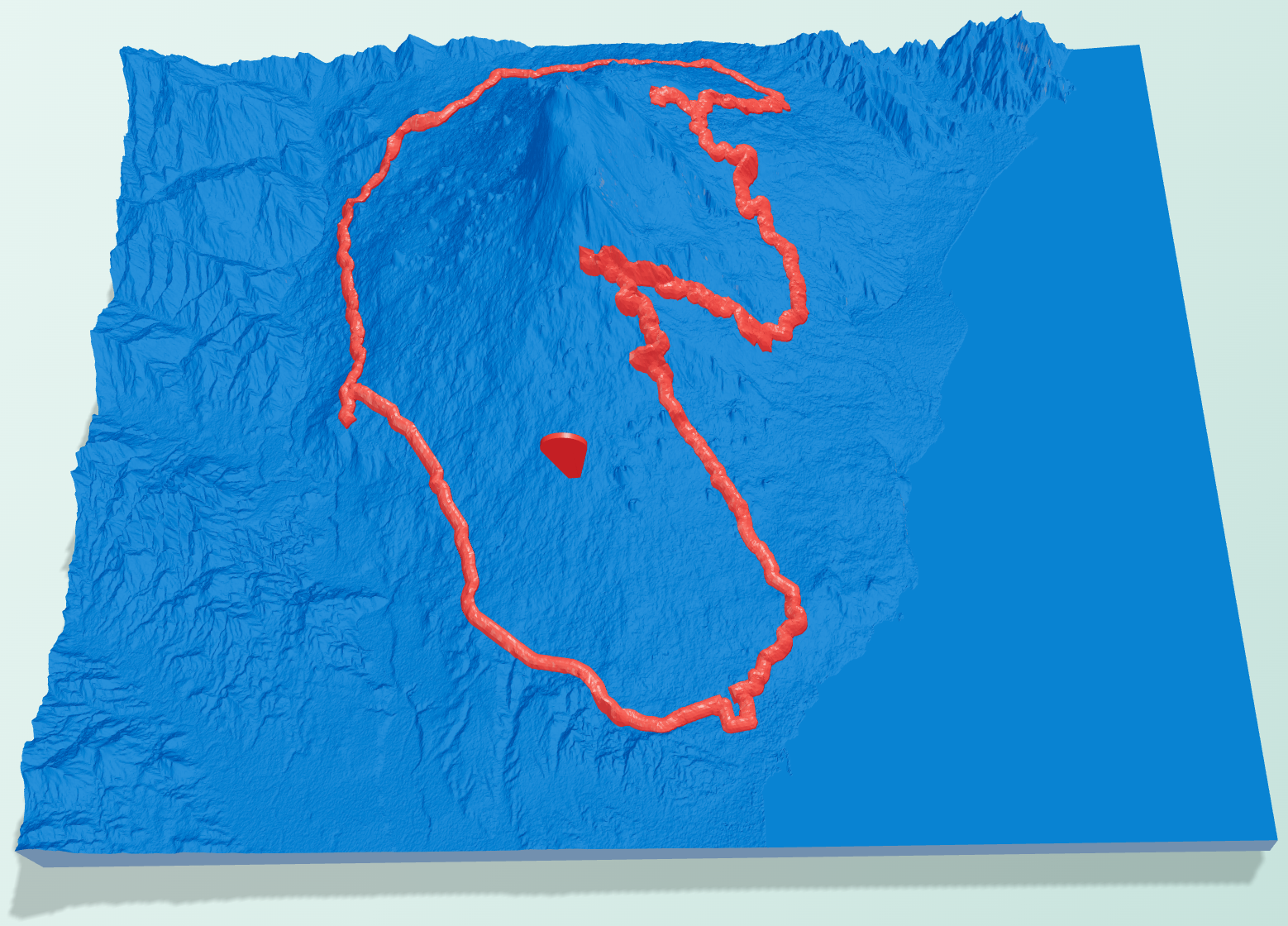
Generated model — default view
This is the model-focused view shown when the preview opens. It displays the generated terrain with its selected model colour and can include independently styled tracks and pins.
Default generated-model view: inspect the terrain geometry and optional map elements before choosing an analysis style.
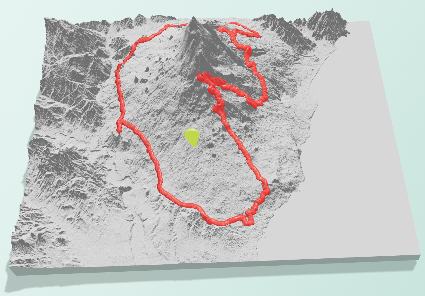
Classic hillshade
Classic hillshade starts with traditional neutral grey, northwest light at 315°, and 45° light altitude. Change the relief colour, intensity, compass direction, and altitude to reveal different terrain structures.
Classic hillshade emphasizes ridges, valleys, and fine surface relief through adjustable simulated illumination.
Slope heatmap
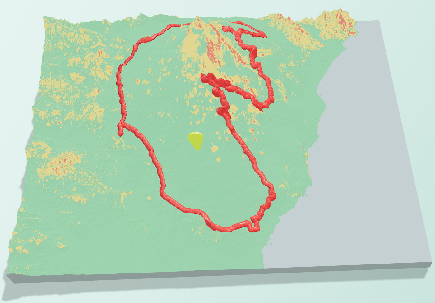
The slope heatmap displays real geographic slope calculated from the smoothed DEM before vertical exaggeration. Green represents 0–15° flat or gentle ground, yellow represents 15–30° moderate slopes, and red represents terrain steeper than 30°. Two independent controls prevent different provenance categories from being confused with flat terrain. Mask source NoData displays genuinely missing and subsequently interpolated cells in neutral grey. Mask classified sea displays boundary-classified flat sea in neutral blue-grey; it is available only when Repair missing sea feature around coastlines produced a sea mask during generation. Disable either control to inspect that category's calculated slope colour. Both controls change only the slope preview—not the terrain mesh, other visualization styles, STL, or 3MF.
Slope heatmap: green, yellow, and red make changes in terrain steepness immediately readable, while masked regions remain visually separate.
Contours & topographic colour
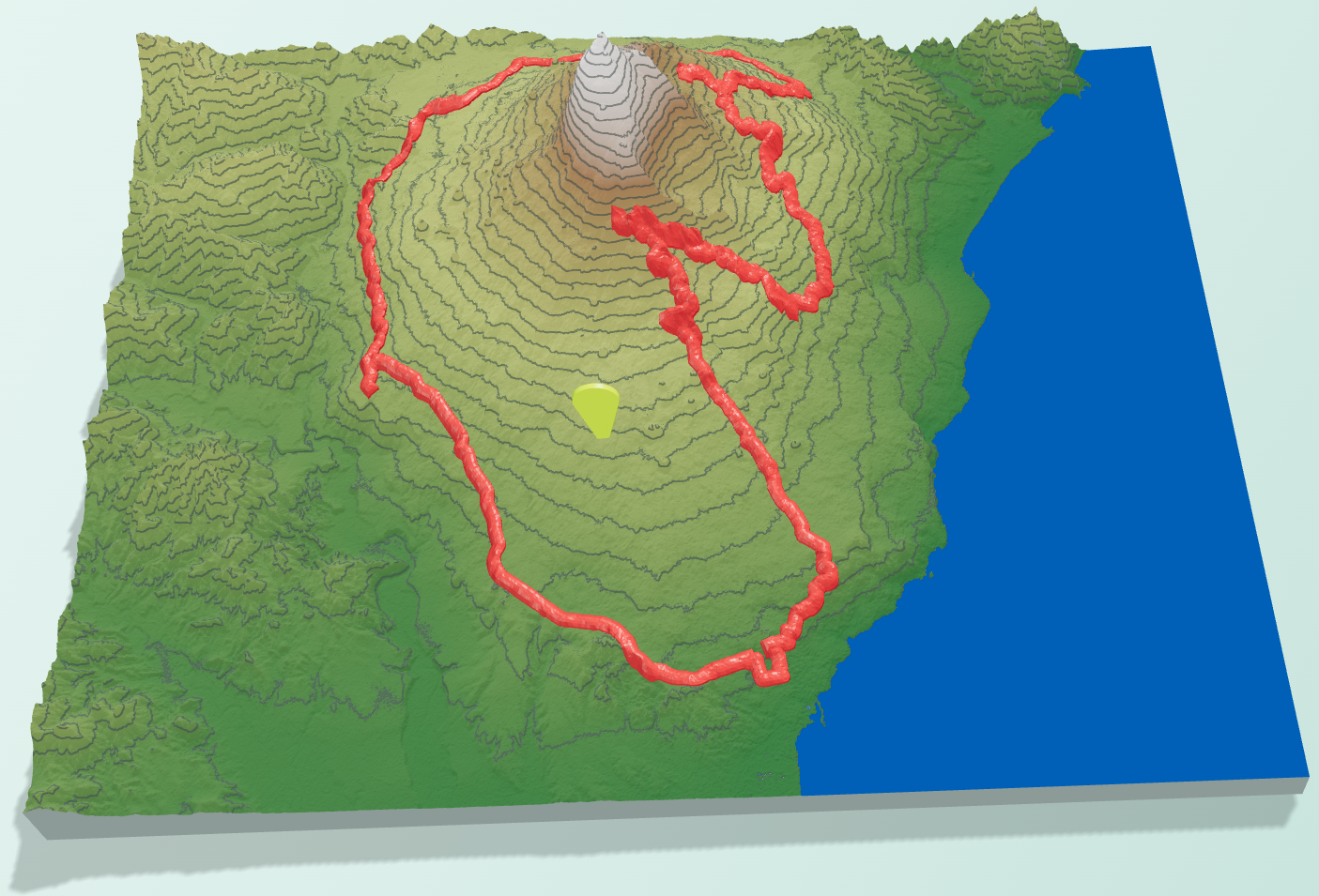
This style draws smooth procedural contour lines from real elevation values. Automatic spacing aims for roughly fifteen readable levels and rounds to familiar cartographic intervals; disable it to enter a manual interval in metres.
Topographic view combines elevation colours and procedural contour lines while keeping tracks and pins visible.
Choose among nine colour scales: Classic Topographic, Printed Atlas, Alpine Relief, Forest & Highlands, Desert Relief, Classic Bathymetry, Deep Ocean, Coast & Land, and Ocean-to-Summit. The final two are hybrid scales permanently anchored to actual zero metres: elevations at or below 0 m—including models that are entirely underwater—use only the blue bathymetric half, while elevations above 0 m and entirely terrestrial models use only the land half. The colour ramp remains clean and uninterrupted without an overlaid coastline marker.
Why DEM elevation is used: GPS altitude is optional and often noisy. The printable route uses
the generated terrain surface as its Z reference so it remains aligned after smoothing, scaling, and vertical exaggeration.
Designed for slicing: each normal track segment is exported as a sealed manifold object rather than a visual line or open surface. In segmented 3MF, routes remain clearly named components; in the combined STL, a true solid union removes internal intersecting faces between the route and terrain. If an exceptional recording still creates mathematically ambiguous geometry—such as an exact repeated retrace—the app preserves and downloads the parts so the slicer can repair them instead of blocking the export.
Browser mode required: printable GPS tracks are currently available in Browser Processing.
Switch to Browser mode before generation, or uncheck the track if you intentionally want a Cloud terrain-only job.
Land, Coast, and Sea Activities
The route always follows the surface represented by the selected DEM. Standard land DEMs may represent the sea
as a flat zero-elevation surface. For cruises, sailing routes, coastal relief, or seabed models, choose
SRTM15Plus, GEBCOIceTopo, or GEBCOSubIceTopo when their bathymetric representation matches your project.
Track Storage and Data Flow
Imported tracks are stored locally in browser IndexedDB so they survive reloads without filling localStorage.
GPX, KML, and GeoJSON routes remain part of the Browser workflow because printable tracks are not currently a
Cloud feature. Deleting a track from the Tracks tab removes its local stored record.
📖 Usage Guide
Follow this sequence from registration to model generation:
Step 1: Create Your Account
Click the "Launch App" button from the landing page or navigation bar.
If you're not logged in, you'll be redirected to authentication.
Register with name, email, and password.
After login, your user menu appears with your initials/avatar.
🎉 Pricing model: Browser creation, full preview, PNG capture, and project JSON are free. Printable Browser files use one pass per exact configuration; Cloud uses credits per submitted job. Both spend the same balance.
Credit purchase checkout: You can pay with a PayPal account or use guest checkout without creating a PayPal account.
You will be redirected to the app with the settings modal opened.
From Main Application
Desktop: open the integrated menu in the right panel and click OT API Key.
Mobile: tap user avatar in the top header and choose OT API Key.
Save the Key
Paste API key in the input field.
Click Save API Key (or press Enter).
Confirm status message shows the key is configured.
How the key is stored and used: saving stores the key in browser session storage and syncs it
to your authenticated Firebase profile. Browser Processing sends the session copy directly to
OpenTopography. Cloud Processing lets the Firebase backend read the profile copy and send it to
OpenTopography on your behalf. Clearing the key in the app removes both copies; deleting the account removes
the profile copy. The key is not used for PayPal checkout.
⚠️ Important: You must be logged in to save and use an API key.
Step 4: Optional Track Upload, Manual Bounding Box, and Pins
Optional: Upload a GPS Track First
Choose Track beside Pin in the desktop map toolbar (or Upload GPS Track on mobile) and select one or more GPX, KML, .geojson, or GeoJSON .json files.
Confirm the track appears on the map; the map automatically fits the imported route. Open the Tracks tab in Map Elements to manage it.
Use the track controls to rename it, choose an activity, set its color, and configure printable width and raised height.
Use show/hide and zoom controls to inspect the route before framing the terrain.
Select the Box Area
Choose Draw Box on desktop (or Draw New Bounding Box on mobile) and place 4 points on the map.
For repeatable limits, choose Set Box on desktop (or Set Bounding Box on mobile) and enter south, west, north, and east directly. The optional name starts empty; Add box assigns the next automatic Box number when no name is entered.
To reconstruct a saved configuration, choose Import project and select the JSON downloaded from an earlier preview.
Use the search tool—or the uploaded track itself—to position the map before drawing.
Review the resulting area value in the box details.
Review GPS tracks in this box. A route is labeled Complete or Partial; use its checkbox to include or exclude it from this box.
Set Bounding Box provides exact, repeatable geographic limits; the optional name becomes the basis of generated filenames.
Optional: Add Pins
Choose Pin on desktop (or Place Pin on mobile) and tap the map to add landmarks, then open the Pins tab to manage them.
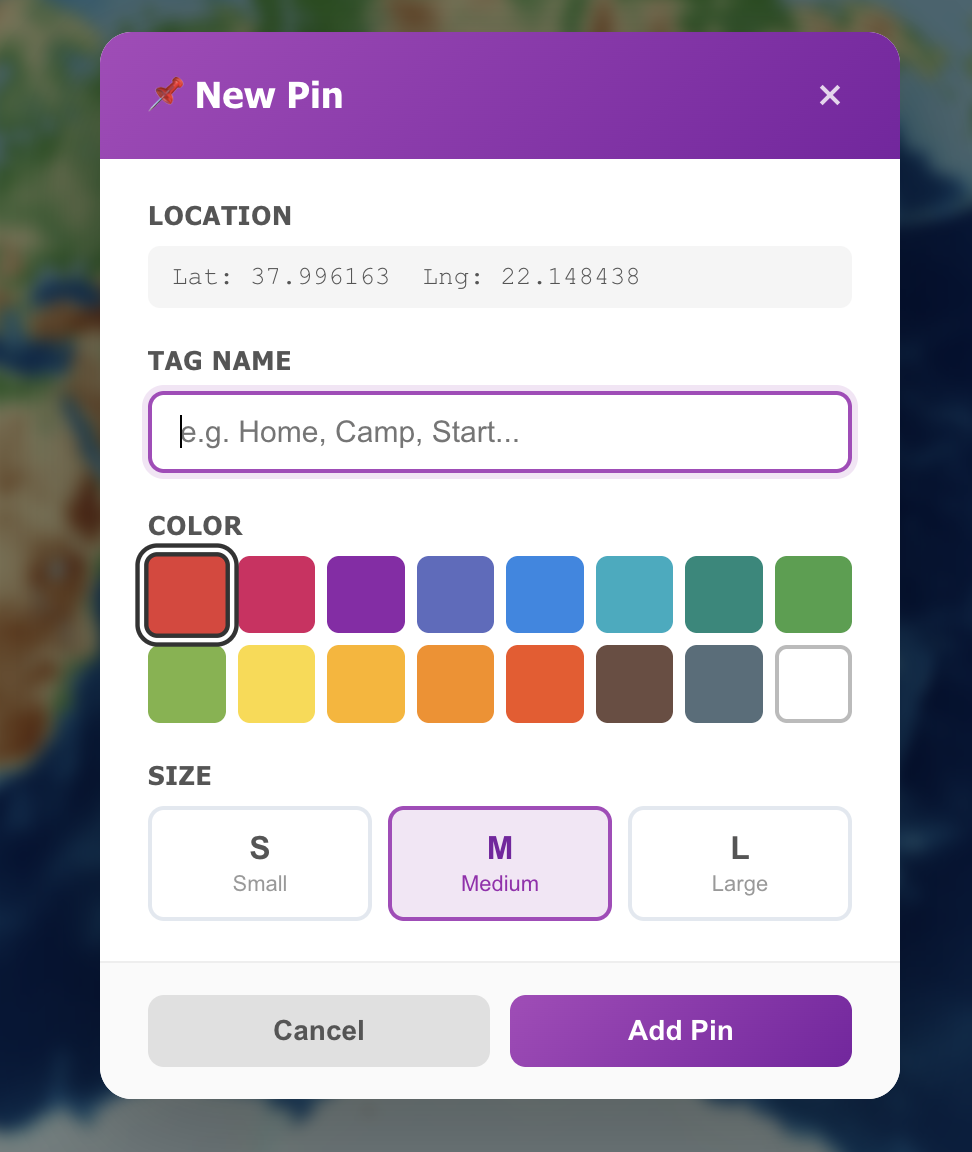
Set pin tag, color, and size.
Use pin list actions to zoom, edit, hide/show, or delete.
Keep pins inside the selected box if you want pin-inclusive exports in Browser mode.
The New Pin dialog records the chosen map position and lets you assign a meaningful tag, print colour, and physical size.
After creating or selecting a box, configure the model parameters in the box panel. These values control the final physical print size, terrain readability, and processing performance:
Width (mm) / Length (mm): define the real-world print footprint of the generated model for this specific box.
Dimensions Link: keeps width/length proportional to the map area ratio, so changing one value updates the other automatically.
Vertical Exaggeration: scales elevation differences along Z. Higher values emphasize relief and cliffs; lower values keep a more realistic vertical profile.
Smoothness: applies terrain smoothing before mesh generation. Increase it to reduce noise and sharp micro-artefacts; keep it lower for more raw terrain detail.
DEM Source: selects which elevation dataset is queried. Coverage, accuracy, and resolution vary by region and source.
Repair missing sea feature around coastlines (Browser only): use it for coastal models when the selected land DEM leaves sea areas empty (NoData) or represents them as flat 0 m regions. It restores boundary-connected missing-data regions or 0 m areas to sea level while preserving underwater elevation data. Enclosed NoData gaps are interpolated, enclosed zero plateaus remain terrain, and legitimate negative elevations are not treated as missing. Leave it disabled for inland models, genuine land close to 0 m, or whenever an edge gap could represent incomplete coverage rather than water. SRTM15Plus and both GEBCO sources preserve their measured bathymetric zero and negative values. The setting is off by default, disabled in Cloud mode, and not included in Cloud job requests.
Resolution Reduction Factor: downsamples input elevation points before mesh creation. Higher reduction is faster/lighter but can remove fine detail.
Composition Mode: chooses model strategy:
Full-Solid: single terrain body.
Topographic: segmented terrain bands for multi-part or multi-color workflows.
Topographic settings (visible only when Topographic mode is selected): configure how elevation is split into geometry bands. This includes:
Band Mode: choose how the terrain is partitioned:
Adaptive: balances band distribution based on terrain elevation distribution; usually best for irregular landscapes.
Equal Step: splits vertical range into equal-height bands; useful for clean, contour-like layering.
Coastal Preserve: keeps the complete low-elevation/coastal range together in the first topography level, then divides the remaining higher relief across the other levels without leaving a vertical gap.
Topography Bands: number of generated terrain bands (in addition to the base).
Coastal Preserve Strength % (conditional): shown only when Band Mode = Coastal Preserve. A low value behaves closer to Adaptive mode. A high value groups a wider coastal elevation range into topography level 1. The base remains a continuous 4 mm solid, and every topography level starts exactly where the previous level ends.
Note: topographic mode currently focuses on geometry banding and no longer uses color scheme selection in this panel.
Cloud Processing Cost (Cloud mode): shows required credits for that specific box before submission.
GPS tracks in this box: lists every intersecting route, shows Complete/Partial status, and stores per-box inclusion choices.
Step 6: Choose Processing Mode
Use the Browser · Local / Cloud · Remote switch below the menu area for a quick change, or open Processing Mode for the complete comparison, shared balance, and credit packs. Both controls remain synchronized. See the
complete Browser vs Cloud capability table
whenever you want a quick recommendation:
Interactive creation and advanced exports: prefer Browser Processing whenever the selected area and DEM are comfortable for your device.
Models with printable GPS tracks: use Browser Processing, regardless of area, because track geometry is currently generated locally.
Boxes above 100 km²: the Browser warning is advisory. Local generation may still work; consider a stronger reduction factor and allow more time.
Projects beyond your device's practical CPU or memory limits: prefer Cloud Processing, which has no fixed app-defined area ceiling.
Step 7: Generate
Check box settings and selected mode.
Click Generate 3D Model.
Follow progress until completion.
Use the large interactive preview to rotate freely in every direction—including roll and underside inspection—and zoom until the terrain is framed the way you want. Rotation and zoom remain anchored to the model's exact three-dimensional centre, while the camera composition places the terrain slightly higher in the stage to provide more useful space during close inspection. Panning is intentionally disabled. Choose Reset view at any time to return to the fitted, raised starting camera, or Save image to download the current view as a high-resolution PNG. The image is created entirely in your browser and is separate from the printable model files.
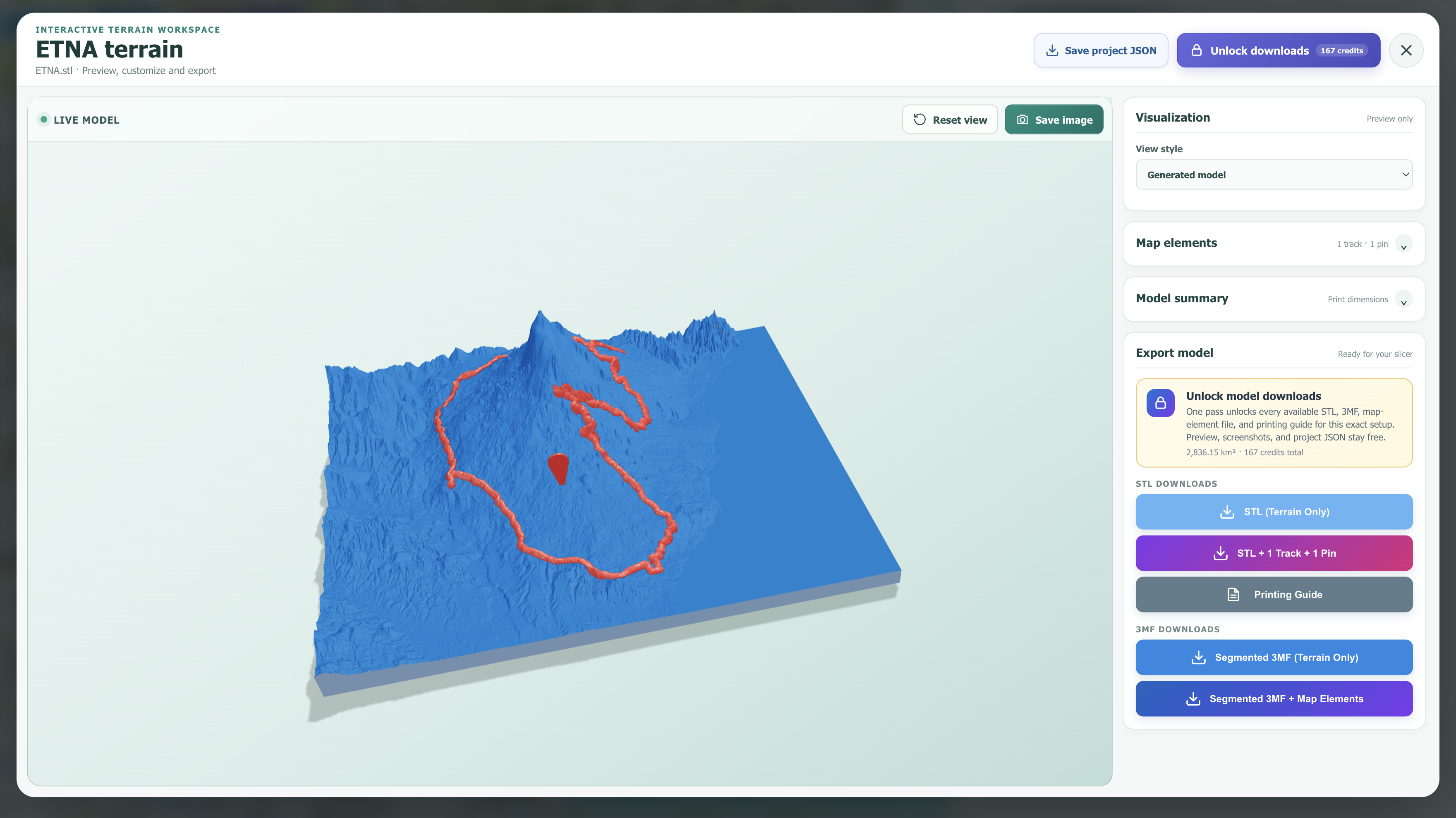
The header identifies the terrain and source file and keeps Save project JSON beside the visually distinct Unlock downloads action. Saving the JSON is free and preserves exact bounds, settings, printable routes, pins, and fingerprint for later import.
Map elements and Model summary both start collapsed so optional presentation controls and technical details do not compete with the model. Expand Map elements to show, hide, recolour, or restore the Original preview colour of individual tracks and pins. Expand Model summary for the DEM, boundary-sea diagnostics, map-element counts, physical dimensions, elevation range, and triangle statistics.
The app checks whether this exact configuration already has a Browser Export Pass. If not, review the displayed area and credit price, then choose Unlock downloads. The authenticated service transiently verifies the complete canonical configuration—including selected printable tracks and pins—recalculates its fingerprint and price, and stores only the entitlement summary rather than the complete geometry. One server transaction charges once; all applicable STL, 3MF, and guide buttons then enable. Regenerating or retrying the identical project does not charge again.
Choose STL (Terrain Only) or STL + Tracks/Pins. Browser exports normally pass strict edge, orientation, volume, manifold, and Boolean-union checks before download. If arbitrary map geometry cannot be normalized universally, a quiet compatibility export preserves all shells for slicer-side repair instead of blocking the file.
In Topographic mode, choose Segmented 3MF + Map Elements to keep the base, watertight elevation bands, tracks, and pins as separate aligned objects.
The model-first preview combines free viewing and image capture with collapsible details, project saving, export unlocking, and the applicable slicer-ready downloads.
Watertight 3MF: topographic terrain bands are closed solid volumes. Their contour walls,
tops, and bottoms are sealed, and adjacent parts meet on the same Z interface so the complete assembly contains no empty terrain regions.
Purchased Models: open it beside your shared balance to restore a locally archived purchased
configuration. Every visible row—including a server entitlement marked Manifest required—includes
Remove from this view for hiding that configuration in the current browser without deleting its
account entitlement. The row disappears from the local list and the visible Purchased counter decreases as well.
This removal is local only;
importing the matching saved project JSON later adds it back, reconstructs the configuration, and restores
its already-purchased downloads without another charge, returning it to the list and counter. Deleting an active workspace box also leaves both
the entitlement and local archive intact.
Slicer-visible names: one 3MF file contains individually named and aligned build items. Terrain parts are base, topo-1, topo-2, and so on. A single map element is track or pin; multiple elements become track-1, track-2, pin-1, pin-2, and so on. The former generic Print Model parent is not written, preventing compatible slicers from copying that generic name onto every part. All build items use the same original coordinates and no transform, so they remain aligned. Open the 3MF as a project and do not choose an optional auto-arrange action that intentionally moves separate objects.
Simple filenames: files identify the name assigned to the box (for example, Box1), whether Full-Solid or Topographic mode was used, and the content included in that download. For Full-Solid mode, the possible combinations are Box1_FullSolid.stl, Box1_FullSolid+Pin.stl, Box1_FullSolid+Track.stl, and Box1_FullSolid-Pin&Track.stl. Topographic downloads follow the same pattern but use _Topographic instead of _FullSolid after the box name and are available as STL or 3MF. Spaces and filesystem-reserved characters are removed from the assigned box name so the downloaded filename remains compact and compatible.
🧭 Printing Tips & Model Orientation
The usual and most stable setup is to place the model with its broad flat base directly on the build plate. This maximizes adhesion, minimizes supports, and is the best starting point for most terrain prints. However, when horizontal layer stepping is highly visible across slopes or fine relief, an edge-on vertical orientation can produce a cleaner-looking terrain face because the layer direction crosses the model differently.
Optional technique: print the terrain vertically
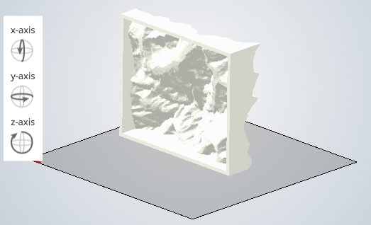
Rotate the model by approximately 90° in the slicer and place its straightest, broadest side or base edge on the build plate, as illustrated below. Do not leave the model floating: use the slicer's Place on face or Lay on face command to establish real contact with the plate.
Example edge-on orientation: the terrain stands vertically instead of resting on its complete bottom base.
Why try it
Vertical orientation can make layer lines less dominant on the main terrain surface and may preserve some ridges, route details, and steep relief more cleanly.
What changes
The print becomes taller, the plate-contact area becomes smaller, and overhangs or map elements may require support. Print stability becomes more important.
Recommended slicer checklist
Choose the longest and flattest available edge as the build-plate contact surface.
Add a generous brim—or a raft when necessary—to resist wobble and detachment.
Use supports only where the slicer preview identifies unsafe overhangs; check pins and raised GPS tracks especially carefully.
Reduce print speed for tall, narrow models and confirm the model fits within the printer's Z-height limit.
Inspect every layer in the slicer preview for unsupported islands, weak contact, and small details that begin in mid-air.
For multipart 3MF files, verify that every part retains the same rotation and alignment before slicing.
Important: vertical printing is an optional surface-quality trade-off, not an automatic improvement for every model. A base-flat orientation remains safer for large, heavy, highly overhanging, or support-sensitive terrain. Compare both slicer previews and choose the orientation that offers the best balance of visible layer direction, adhesion, support marks, print time, and stability.
🔄 End-to-End Processing Flows
Once you have selected a mode, follow its operational sequence below. For feature availability and the reasoning
behind each workflow, use the capability comparison.
Browser Processing Flow
Activate Browser Processing in Processing Mode.
Optionally upload GPX, KML, or GeoJSON tracks, then manually draw a box and select the Complete/Partial tracks to include.
Generate locally in your browser (Web Worker path).
After completion, inspect and save PNG/project JSON for free. Then reuse an existing entitlement or unlock one Browser Export Pass for the exact configuration.
With the pass unlocked, export:
STL terrain only
STL + selected GPS tracks + pins as one printable file
Watertight segmented 3MF terrain
Segmented 3MF + Map Elements, with tracks and pins as separate aligned objects
Printing guide TXT
Cloud Processing Flow
Switch to Cloud Processing.
Confirm the shared balance has enough credits; buy a pack only when needed (PayPal account or guest checkout, no PayPal registration required).
Review Cloud Processing Cost for the selected box.
Generate to submit async cloud job.
Monitor job in Cloud Jobs and download STL when status is Completed.
Safe submission: if a printable GPS track is selected, Cloud submission stops before credits
are charged. Switch to Browser Processing for the route-inclusive model, or intentionally uncheck the track for
a terrain-only Cloud job.
🖨️ Get 3D Printing Cost Estimates
After downloading your STL, you can estimate print costs using the free Print-Calculator tool. For models generated by this service, there is currently a required preparation step before the estimate is accurate.
Free Print-Calculator Tool: Open Print-Calculator
from navigation at any time.
Compatible files: STL, OBJ, and 3DS from this app or other sources.
Important current behavior: when the model comes from this tool, import it into a slicer first, then export it to a compatible format (for example STL/OBJ/3DS as supported by Print-Calculator) before estimating cost. If you skip this conversion step, the estimate may be incorrect or errors can occur.
This extra conversion procedure is only needed at the moment for models generated by this service. Cost estimation works correctly with other models; root-cause analysis for this specific generator flow is still in progress.
Open Print-Calculator.
Import the generated model into your slicer software.
Export the model from the slicer in a Print-Calculator compatible format (STL/OBJ/3DS).
Upload that exported file in Print-Calculator, then enter model/material parameters.
Review instant estimate and request a personalized quote if needed.
🌍 DEM Data Sources
The application supports multiple Digital Elevation Model sources, each with different coverage and
resolution. Below you'll find detailed information about each DEM family:
SRTM Family (Shuttle Radar Topography Mission)
An SRTM DEM is a Digital Elevation Model created from data collected by NASA's Shuttle Radar Topography
Mission (SRTM) in 2000. It provides near-global elevation data for most of the world at resolutions of 3
arc-seconds (~90m) and 1 arc-second (~30m), filling gaps in elevation data to provide a continuous
topographic surface. To be noted that SRTM15PLUS integrates the original Shuttle Radar Topography Mission
(SRTM) land data with improved ocean bathymetry, which is derived from a combination of direct shipboard
measurements and predicted depths using satellite altimetry.
SRTMGL3: SRTM GL3 90m resolution
SRTMGL1: SRTM GL1 30m resolution
SRTMGL1_E: SRTM GL1 Ellipsoidal 30m resolution
SRTM15Plus: Global Bathymetry SRTM15+ V2.1 500m resolution
ALOS World 3D (AW3D30)
AW3D30 is a global digital surface model (DSM) with a 30-meter (1 arcsec) horizontal resolution, generated
from satellite stereo images by JAXA (Japan Aerospace Exploration Agency).
AW3D30: ALOS World 3D 30m resolution
AW3D30_E: ALOS World 3D Ellipsoidal 30m resolution
NASADEM
NASADEM (NASA Making Earth System Data Records for Use in Research Environments) is a digital elevation
model (DEM) that provides global, near-global land elevation data at a resolution of 1 arc second
(approximately 30 meters). It is a modernization of the original Shuttle Radar Topography Mission (SRTM)
DEM, using improved processing techniques.
NASADEM: NASADEM Global DEM at approximately 30m resolution
Copernicus DEM
The Copernicus DEM is a Digital Surface Model (DSM) that represents the Earth's surface, including
buildings, vegetation, and other infrastructure, in a 30-meter or 90-meter resolution format.
COP30: Copernicus Global DSM 30m resolution
COP90: Copernicus Global DSM 90m resolution
European Digital Terrain Model (EU_DTM)
The European Digital Terrain Model (EU_DTM) is a 30-meter resolution model representing the bare-earth
surface of Continental Europe, developed by Dr. Tom Hengl and the OpenGeoHub Foundation, using an Ensemble
Machine Learning (EML) algorithm trained on various Digital Elevation Models (DEMs) and elevation data from
GEDI and ICESat-2. Unlike the older EU-DEM, which was a Digital Surface Model and is no longer maintained,
the EU_DTM specifically models the ground's terrain by removing vegetation and buildings, making it suitable
for analyses requiring the underlying topography of the landscape.
EU_DTM: DTM 30m resolution (Continental Europe only)
GEDI (Global Ecosystem Dynamics Investigation)
The Global Ecosystem Dynamics Investigation (GEDI) produces high resolution laser ranging observations of
the 3D structure of the Earth. GEDI's precise measurements of forest canopy height, canopy vertical
structure, and surface elevation greatly advance the ability to characterize important carbon and water
cycling processes, biodiversity, and habitat. GEDI was funded as a NASA Earth Ventures Instrument (EVI)
mission. It was launched to the International Space Station in December 2018 and completed initial orbit
checkout in April 2019.
GEDI_L3: DTM 1000m resolution
GEBCO (General Bathymetric Chart of the Oceans)
The GEBCO DEM is a 15 arc-second resolution global elevation model that provides continuous coverage of
both ocean depths (bathymetry) and land/ice surface heights (topography), with negative values representing
water depths and positive values representing land/ice heights. Developed by the General Bathymetric Chart
of the Oceans (GEBCO), it's a composite of diverse data sources, including satellite-derived gravity and
ship-track soundings.
GEBCOIceTopo: Global Bathymetry 500m resolution (includes ice topography)
GEBCOSubIceTopo: Global Bathymetry 500m resolution (sub-ice topography)
Choosing the Right Source
For detailed terrain: Use SRTMGL1, NASADEM, COP30, or AW3D30 (30m resolution)
For larger areas: Use SRTMGL3 or COP90 (90m resolution)
For coastal areas and bathymetry: SRTM15Plus or GEBCO sources include ocean depth data
For mountains: NASADEM or COP30 provide excellent detail
For European terrain: EU_DTM provides bare-earth surface modeling
For polar regions: GEBCO sources include ice topography data
For vegetation analysis: GEDI_L3 includes canopy height information
💡 Tip: Data quality and availability may vary by location. If one source doesn't work
well, try another for better results. Each DEM source has its strengths depending on your specific use
case and geographic area of interest.
🌊 Understanding “Repair missing sea feature around coastlines”: Use it for coastal models when the selected land DEM leaves sea areas empty (NoData) or represents them as flat 0 m regions. It restores boundary-connected missing-data regions or 0 m areas to sea level while preserving underwater elevation data. In Browser mode, the option performs a conservative four-neighbour search starting at the DEM boundary and reconstructs only connected candidate cells as flat sea.
Enable it when the preview from a land DEM contains missing or incorrectly filled ocean around a coastline.
Leave it off for inland models, genuine bathymetric sources, or data whose boundary gaps may be incomplete coverage rather than water.
Check the result: the model summary reports NoData-sea, zero-value-sea, and enclosed interpolated cells separately, making the applied repair visible.
Preview behaviour: a dedicated mask keeps reconstructed sea at exactly 0 m through reduction and smoothing. Coast & Land and Ocean-to-Summit use their first clear-blue colour for this water, suppress the otherwise dark zero-metre contour on it, and retain normal depth colouring for genuine bathymetry.
The setting is Browser-only. Cloud mode keeps its established interpolation pipeline, the checkbox is disabled, and no coastal-repair value is sent to Firebase Functions.
🔧 Troubleshooting
Common issues and their solutions:
API Key Issues
❌ "Invalid API Key" or "Unauthorized" Error
Verify your API key is correctly copied from OpenTopography (32-character hexadecimal string)
Check that there are no extra spaces before or after the key
Ensure your OpenTopography account is active and the API key hasn't expired
Try generating a new API key from the OpenTopography portal
❌ API Key Not Saving
Make sure you're logged into the application
Check that your browser allows local storage/account sync (private/incognito mode may restrict
persistence)
Clear your browser cache and try again
Model Generation Issues
❌ "No Data Available" for Selected Area
Try a different DEM source - not all sources cover all regions
For ocean areas, use SRTM15Plus or GEBCO sources
For European terrain, try EU_DTM
Verify your bounding box coordinates are correct
❌ Processing Takes Too Long or Freezes
Reduce the area size if practical, or switch to Cloud mode when the project exceeds your device's comfortable limits; Browser mode has no documented hard maximum
Increase the Resolution Reduction Factor (e.g., 3 or 4 instead of 2)
Close other browser tabs to free up memory
Try using a desktop browser instead of mobile for larger areas
❌ Model Appears Flat
Increase the Vertical Exaggeration value (try 2x or 3x)
Check if the selected area actually has elevation variation
Try a higher resolution DEM source like SRTMGL1 or COP30
❌ Pins Are Missing in the Downloaded File
Use the purple combined STL + Track(s)/Pin(s) button in the download modal
Ensure pins are visible and located inside the selected bounding
box
If needed, use the pin list to zoom and verify each pin position before regenerating
Important: pins in merged STL and segmented 3MF are currently Browser mode export options
❌ A GPS Track File Will Not Import
Confirm the filename ends in .gpx, .kml, .geojson, or .json and that its content matches that format
For GPX, include a track segment or route with at least two valid points; for KML, include a LineString or gx:Track; for GeoJSON, include a LineString or MultiLineString
KML and GeoJSON point geometries are intentionally ignored; create points of interest with the pin system
The current limits are 10 MB and 100,000 usable line points per file
Re-export proprietary activity data as GPX 1.1, KML, or GeoJSON if necessary
❌ GPS Track Does Not Appear in a Bounding Box
Use the track's ⌖ Zoom control and compare its route with the box
Edit the box corners so at least one route segment intersects the box
A segment crossing the box is detected even when its original recorded points lie outside
Check that the route has not been deleted; hiding it affects map display but does not remove association
❌ GPS Track Is Missing in the Downloaded Model
Use Browser Processing; printable GPS tracks are not currently generated by Cloud jobs
In the bounding-box card, confirm the track appears as Complete or Partial and its checkbox is selected
Use the combined STL + Track(s)/Pin(s) button or Segmented 3MF + Map Elements, not the terrain-only button
Increase Track width or Raised height if the path is present but too fine for the slicer's current nozzle/profile
❌ Segmented 3MF + Map Elements Is Missing
3MF exports are available only in Topographic mode
Ensure at least one selected GPS track or pin intersects the selected bounding box
Use Segmented 3MF + Map Elements to export terrain bands, tracks, and pins as separate aligned objects
Important: segmented 3MF exports are currently Browser mode only
❌ Slicer Reports Empty Areas or Open Surfaces in an Old 3MF
Regenerate the 3MF with the current version; older segmented files used the previous surface-slice implementation
Current terrain bands are closed manifold solids with sealed contour walls, top surfaces, and bottoms
Adjacent bands now meet exactly without gaps or artificial overlap
Confirm that the current file shows parts named base, topo-1, topo-2, and so on; older names indicate an older export
❌ Slicer Asks to Repair an STL or 3MF
Regenerate the STL with the current Browser version; older combined files could contain individually closed but intersecting shells
The current exporter repairs face orientation, requires every edge to have exactly two incident faces, validates positive volume, and passes the result through a manifold geometry kernel
Terrain, GPS routes, and pins are now Boolean-unioned so hidden internal intersection faces are removed
Circular imported activities are recognized as closed sweeps, so repeated start/end coordinates no longer create overlapping end caps
Real-world recordings can still contain exact retraces, self-overlaps, or other geometry that cannot be repaired universally. In that exceptional case, the app quietly downloads a part-preserving compatibility file instead of blocking your work; the slicer may then offer its own repair action
Inspect the slicer's repaired layer preview—especially the route, model underside, and contact with the terrain—before printing. If it looks correct, save the repaired slicer project or re-export the repaired mesh
Browser Export Pass & Project Recovery
❌ Download Buttons Remain Locked
Wait for the entitlement check to finish and confirm you are signed in.
Review the required credits shown in the preview; buy a shared credit pack if the balance is insufficient.
If the unlock request fails, no credit is charged. Retry after connectivity is restored.
An identical purchased project should unlock automatically. If it does not, import the original JSON rather than manually approximating the box.
❌ Purchased Model Says “Manifest Required”
The account entitlement still exists, but complete route, pin, and model settings were removed from this browser or purchased on another device.
Choose Import project and select the JSON saved from the original preview.
The app recalculates and verifies the fingerprint; a modified/incomplete file is rejected instead of being attached to the wrong purchase.
Download Issues
❌ STL File Won't Download
Check that pop-up blockers aren't preventing the download
Try a different browser if the issue persists
Ensure sufficient disk space is available
Display Issues
❌ Preview Image Won't Save
Wait until the interactive model has finished loading and the Save image button is enabled
Allow automatic downloads for the site if the browser blocks the PNG
The saved image uses the current rotation, zoom, and slightly raised composition; use Reset view before saving if you want the original fitted view
❌ 3D Preview Not Loading
Ensure WebGL is enabled in your browser
Update your graphics drivers
Try disabling hardware acceleration in browser settings
Use a different browser (Chrome typically has the best WebGL support)
💡 Still having issues? Contact the developer for personalized support via the
contact page.
👨💻 Credits
Created by Carmelo Sammarco (Sicilian4Ever)
This application represents the intersection of geospatial science and modern web technology. Built with
passion for cartography, 3D printing, and open-source software.
📧 Support: For issues and questions contact the developer.